Assembly Instructions for PCB Version 5
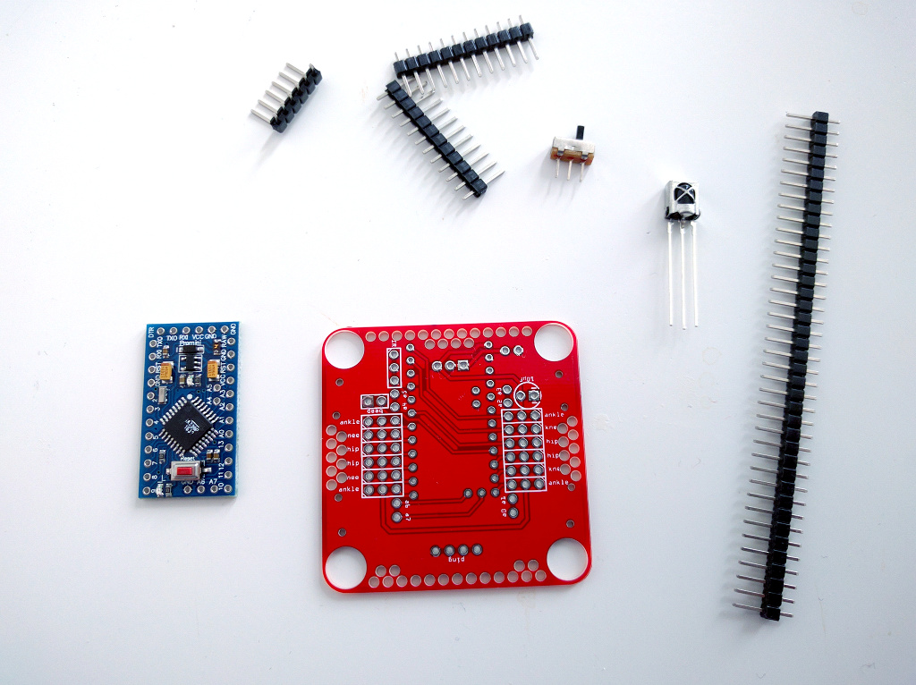
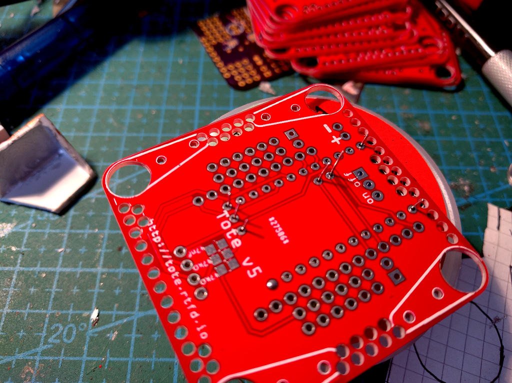
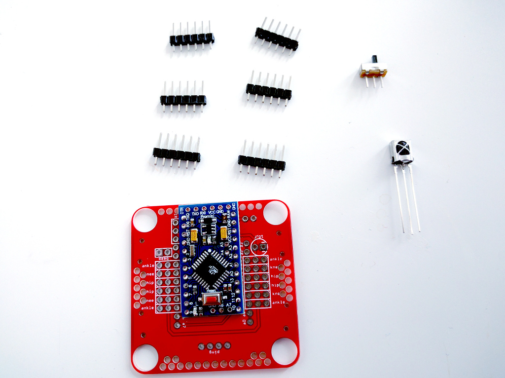
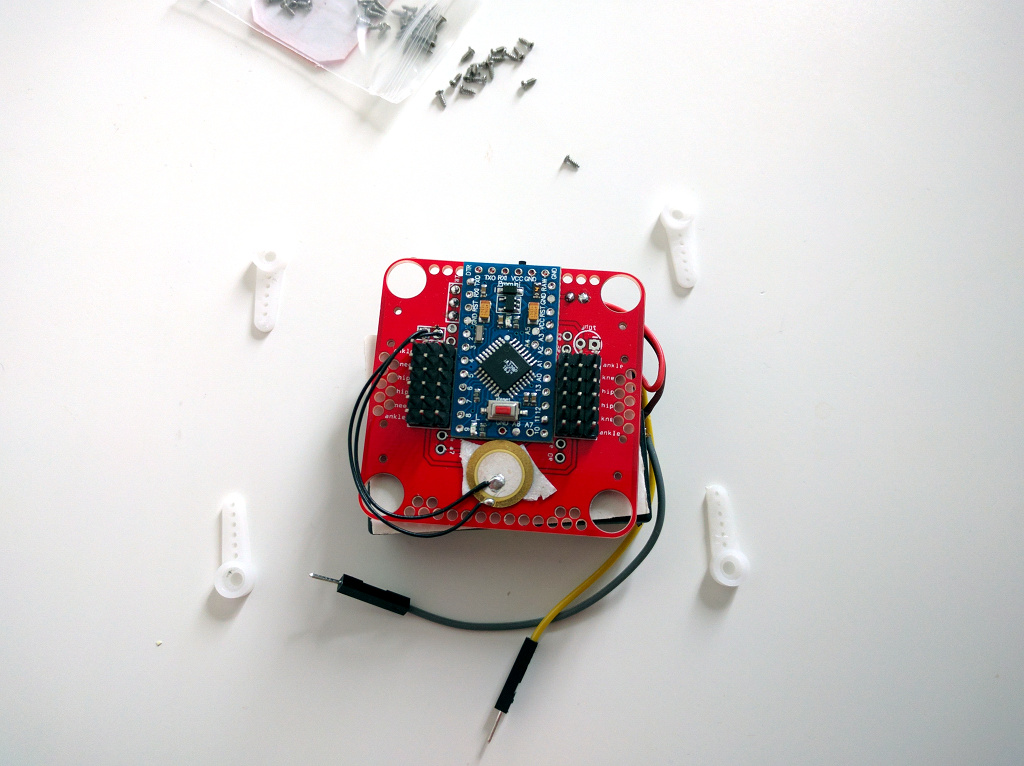
Those instructions are for version 5 of the PCB. You can tell you have this version, because it’s red and has a “Tote v5” written on it. Start by preparing all the components. At the minimum, you will need these:
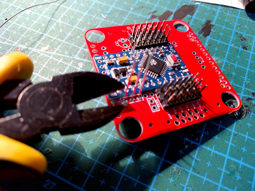
Solder the Microcontroller Board Directly
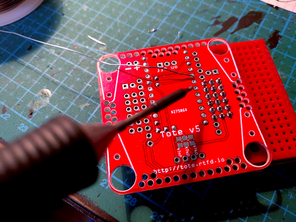
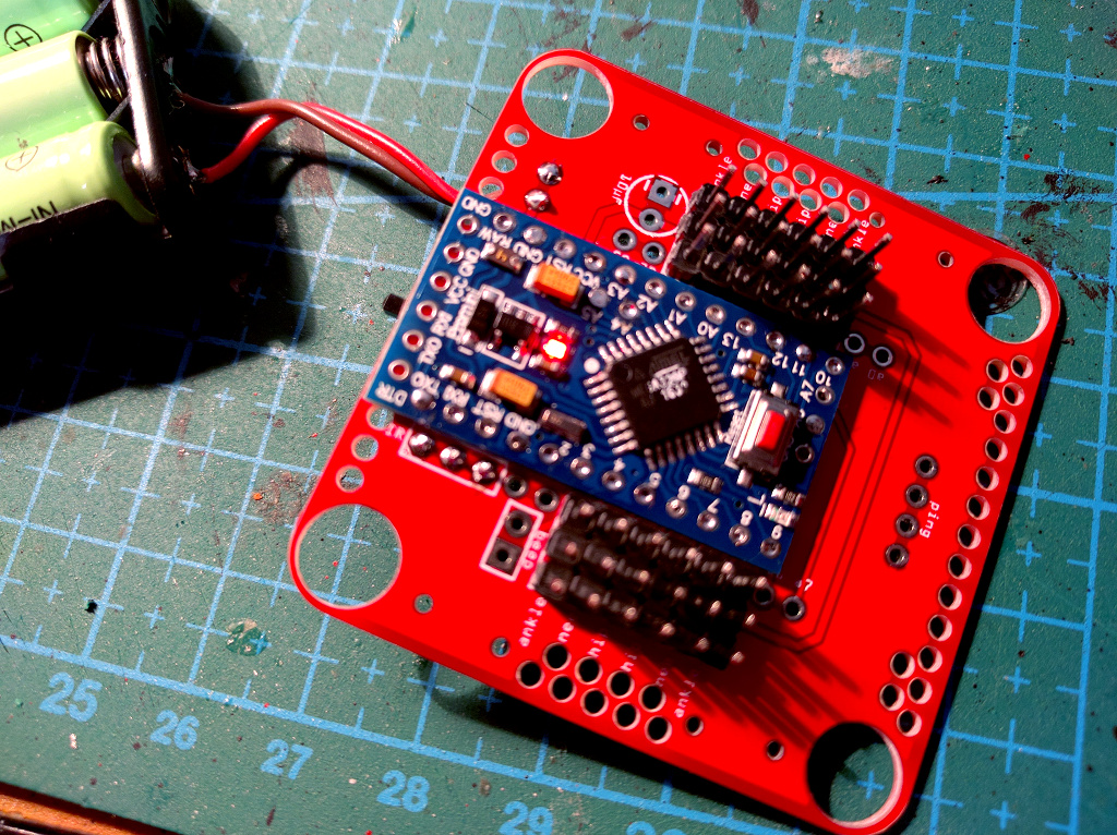
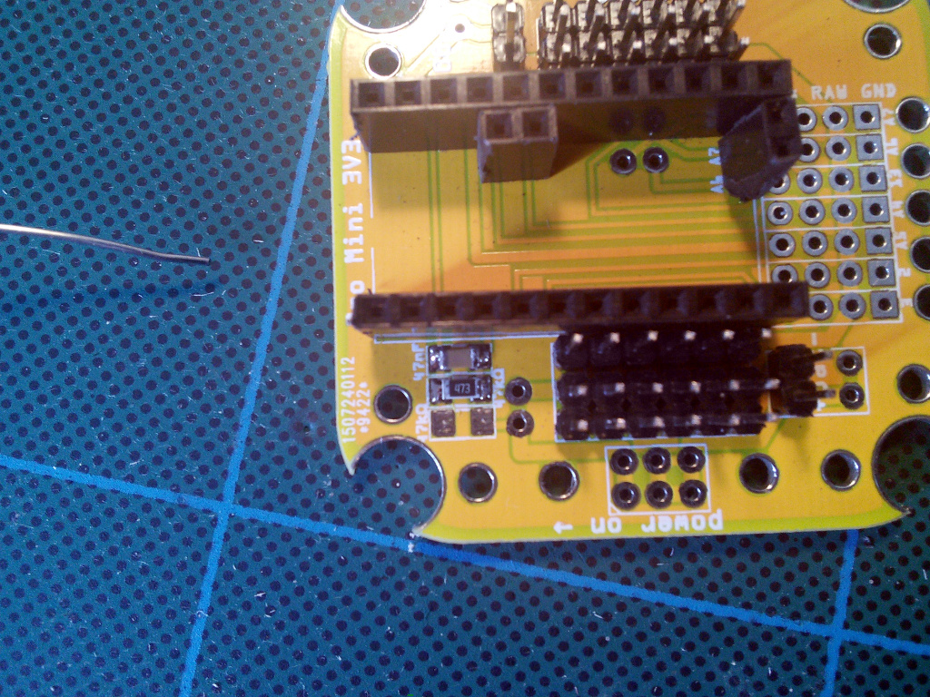
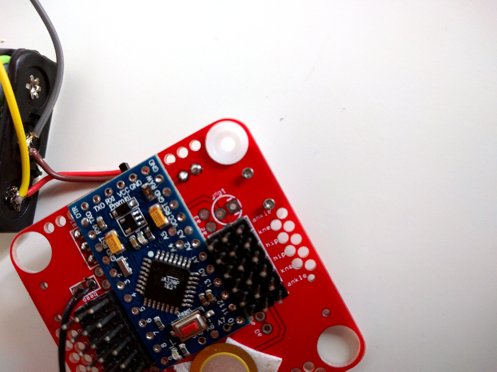
We are going to start with the hardest part – soldering the microcontroller board to the main board. Align the Pro Mini board with the holes carefully, and put a piece of solder wire through the hole:
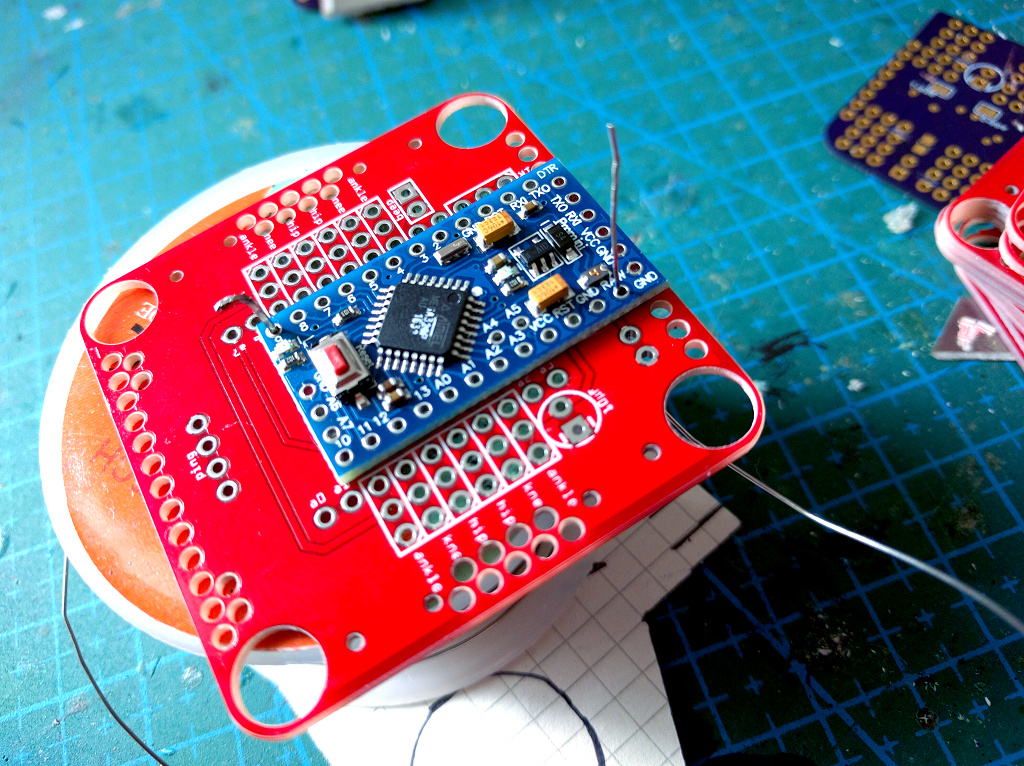
It’s recommended to start not with the corner hole, like in the photo above, but with the two holes in the center. You can insert some pins into other holes to make sure they remain properly aligned. Now touch the solder wire with your hot soldering iron:
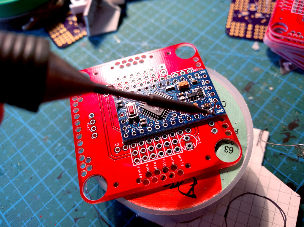
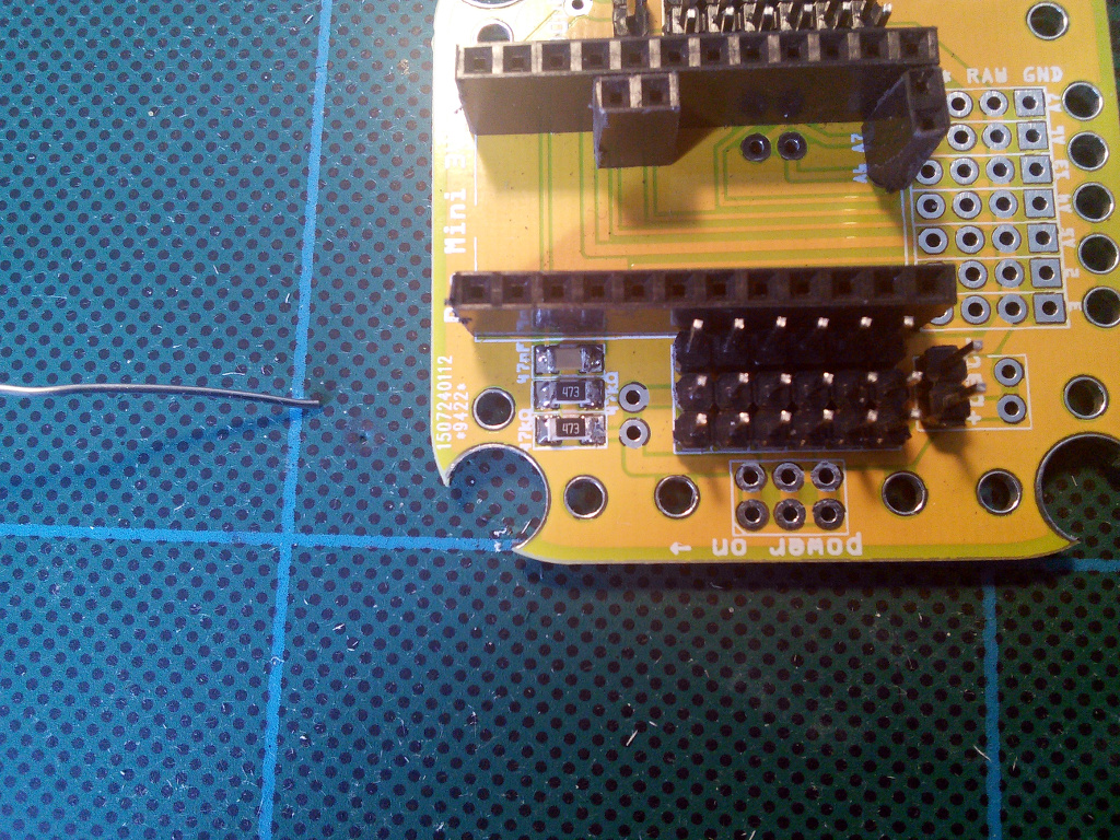
Then cut the wire a couple of millimeters from the board, and repeat for other holes. Now flip the board on the other side, and touch the wires with your iron:
Once you finish all 24 holes, the microcontroller board is soldered.
The Servo Headers
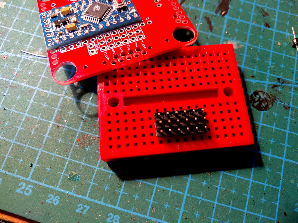
You will need six pin male pin headers, with six pins each. You can obtain four of them headers by breaking in half the pin headers that were added to your Pro Mini module, however, you will need at least two more.
The best way to hold the pins in place during soldering is to simply use a breadboard. If you don’t have a breadboard, you can use a sticky tape or simply hold them with your hand (be careful to not burn yourself).
Place the board over the pins, apply some flux to them, and then touch one of the pins with your soldering iron. When it becomes hot, touch the solder wire to the pin, and let it melt and fill the hole around the pin. Repeat for all the pins.
Repeat that for all six of the headers.
Infra-red Sensor
Insert the sensor exactly the way shown on this photo – the order of its pins is important:
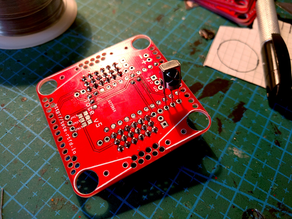
Solder it the same way as the pins, then cut off the excess wires:
Power Switch
Bend the legs of the power switch sideways, and place it on the board so that it sticks out a little bit. This time it doesn’t matter which way you place it:
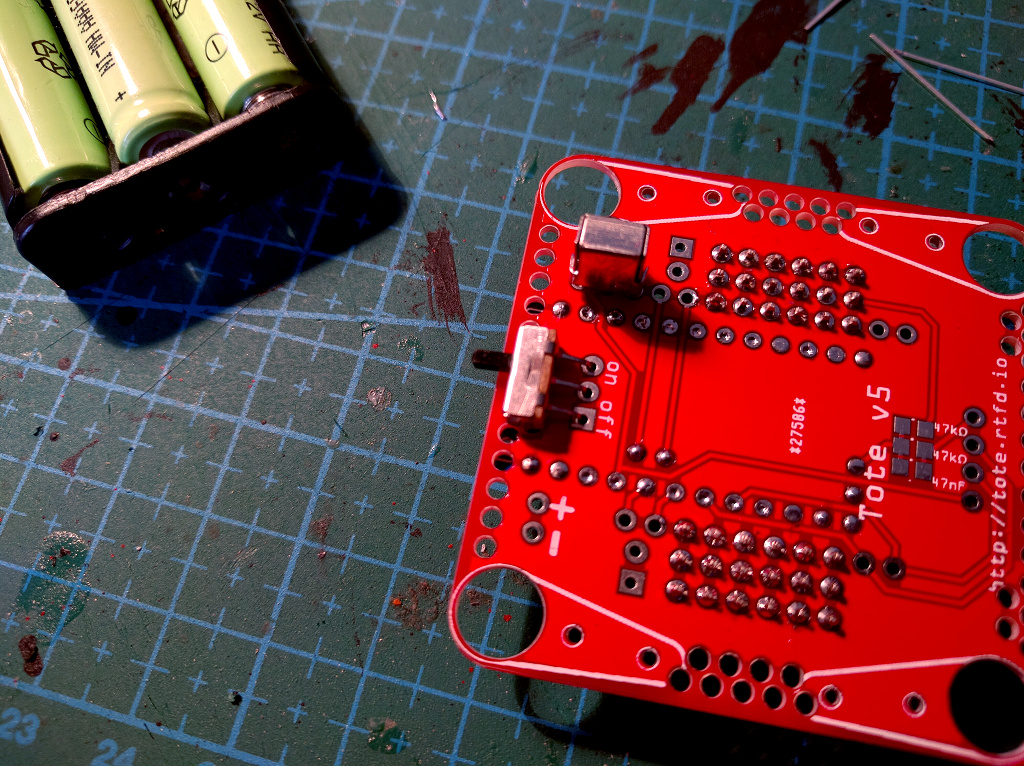
Solder it the same way as the pins.
Battery Connector
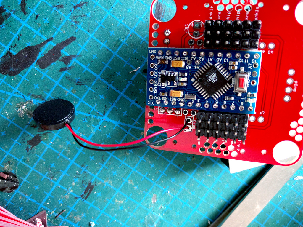
Depending on the batteries you are going to use, you may either prefer a pin header:
Or just solder the wires directly. Make sure to use the red wire for the plus, and the brown (or black) wire for the minus:
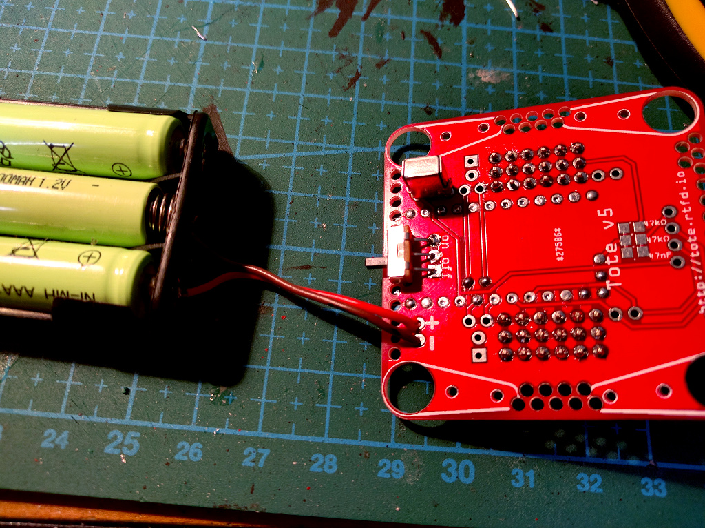
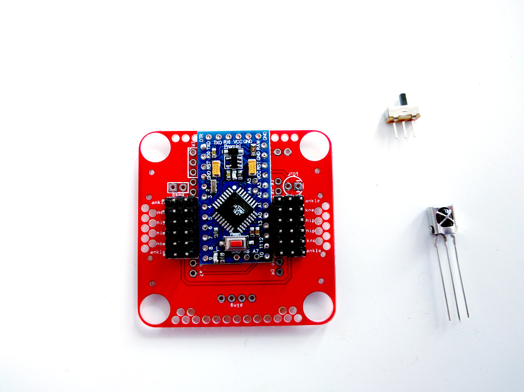
Your finished board should look like this:
Optional Battery Monitoring Circuit
Since the battery has higher voltage than the 3.3V our Pro Mini uses, we need to lower it to be able to measure it, using a voltage divider. This circuit consists of two 47kΩ resistors and one 47nF capacitor in the upper left corner of the board:
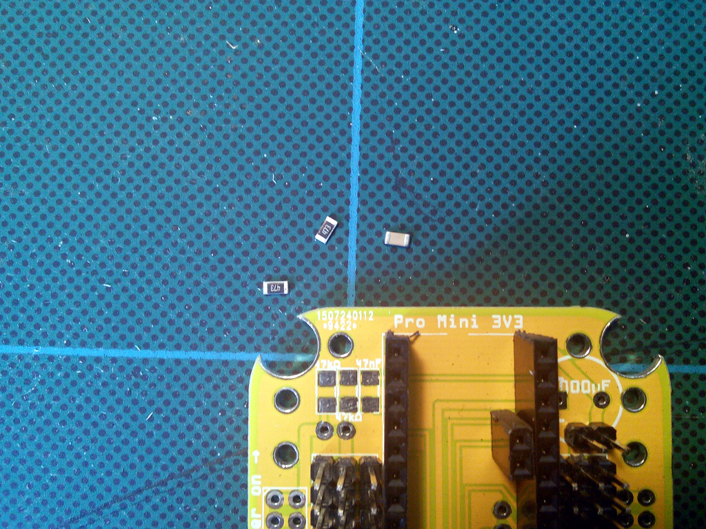
Place each of the parts in the right spot, and solder one end of it:
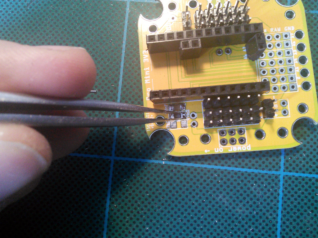
When it’s in the right position, solder the other end:
Repeat that for each of the parts:
This is only needed if you are using a LiPo battery. You will also need to uncomment the battery monitoring code in the robot’s program.
Optional Anti-brownout Capacitor
This capacitor makes sure that the microcontroller has enough current even when the servos momentarily use all the battery can give. It has its place in the upper right corner of the board. Pay attention to the markings on the capacitor and the board, to make sure the negative lead goes into the right hole – electrolytic capacitors are polarized and connecting them wrong may make them explode.
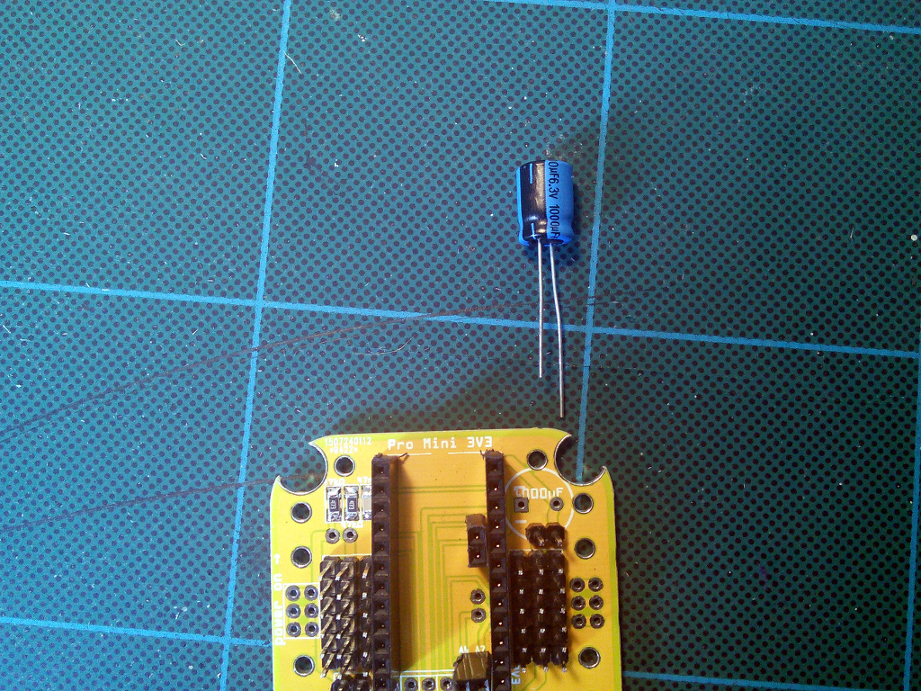
The negative lead is usually marked with a dark strip.
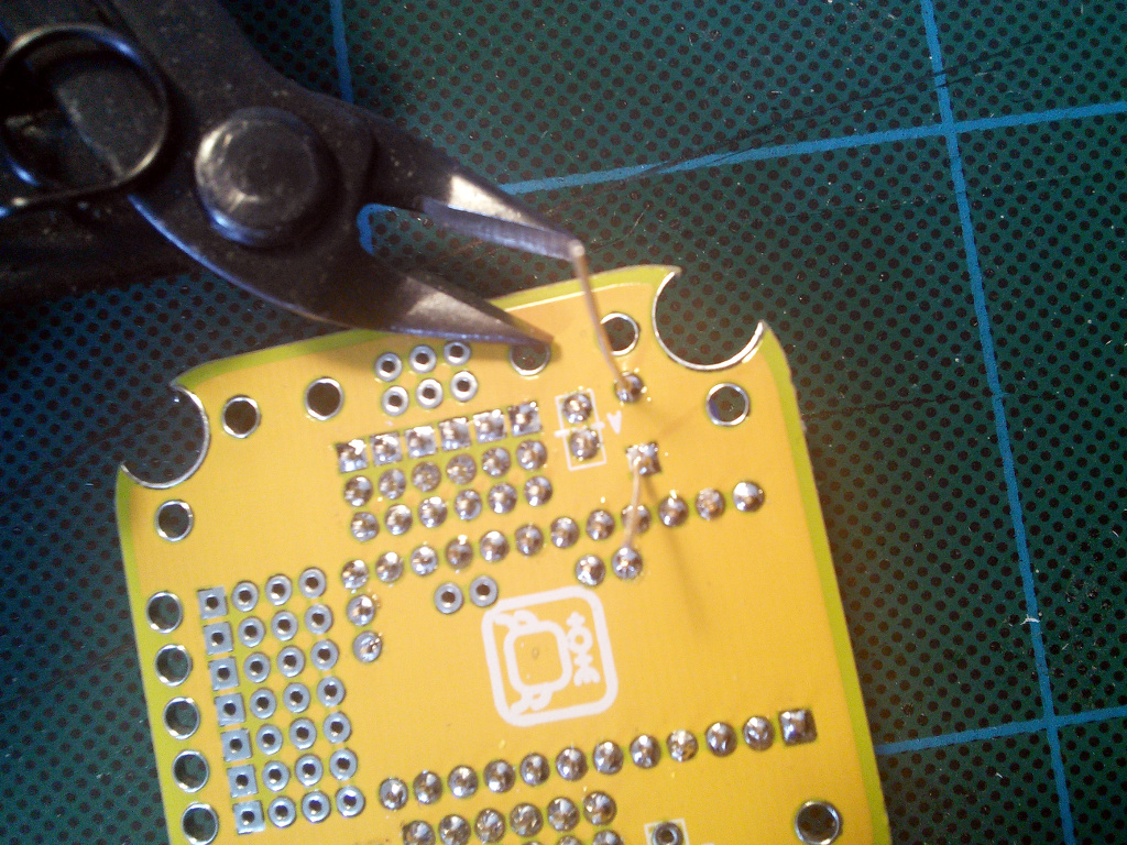
Cut off the excess leads from the other side.
Servo Horns
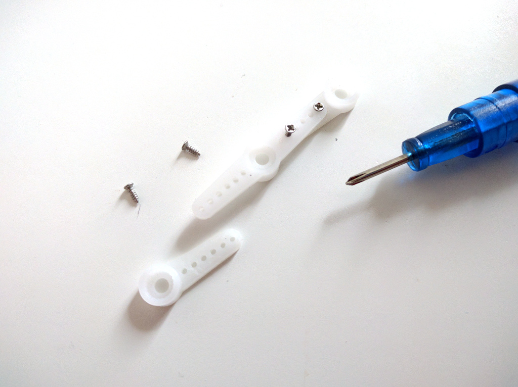
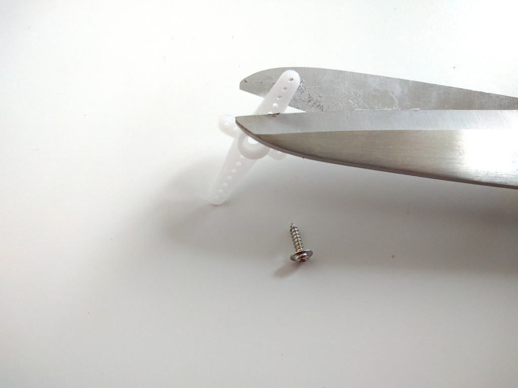
Instead of using the large screws that came with your servos, it’s much better to get some M1.2x4mm screws, and use those. If you still want to use the servo screws, you will need to enlarge the holes in the PCB and in the servo horns. You can do it with a metal file.
Attach the horns with two screws each:
Programming
To program the microcontroller, you will need to connect the USB programmer to the header at the top of the board:
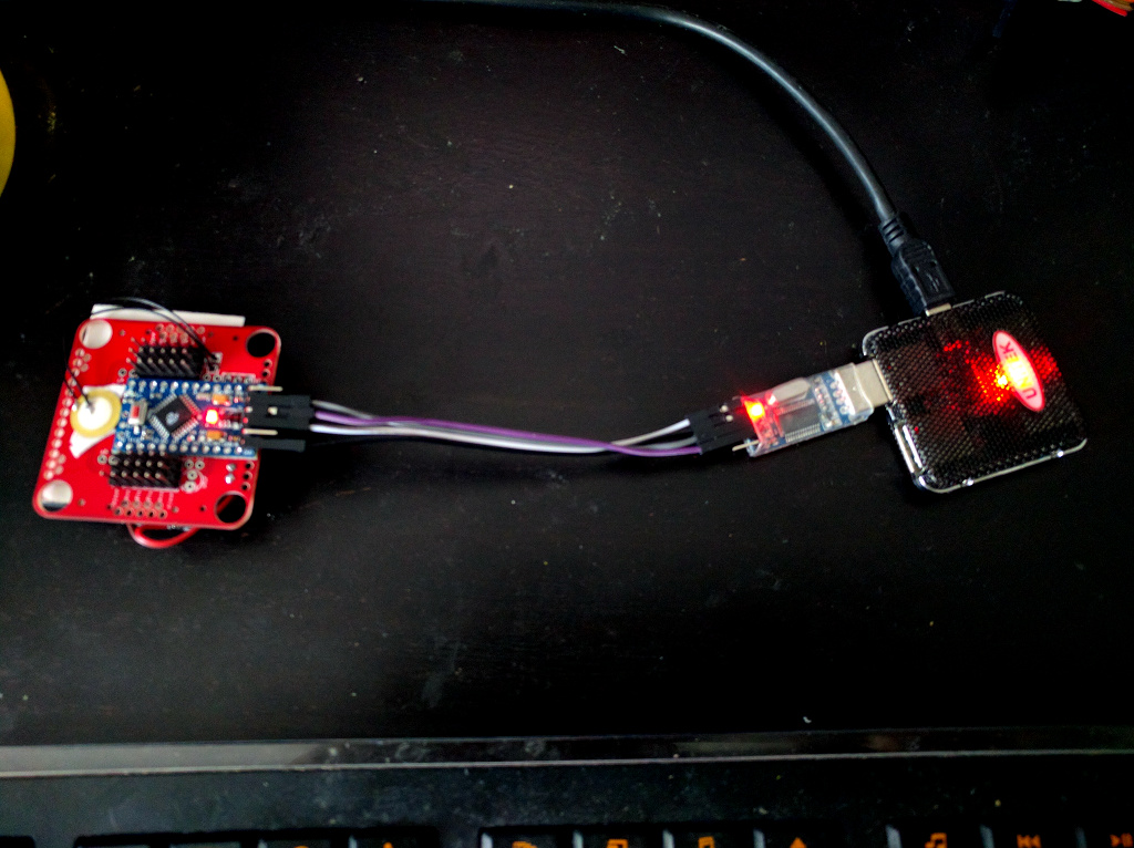
The connections are:
- RX ↔ TX
- TX ↔ RX
- GND ↔ GND
- VCC ↔ 3V3
- DTR ↔ DTR (if available)
If your programmer doesn’t have a DTR pin, you will need to press the reset button on the board manually, just after your program compiles but before it starts programming. This may require several tries.
I usually don’t solder the header to the programming pins, because you only use them once – you can get good enough connection by just putting them in the holes and pressing with your hand. Once programmed, you can remove them.
To program, open in Arduino IDE the v5/v5.ino file. For assembly and tuning,
you will want to edit the file and change the robot_mode variable to 2.
This will make the robot simply stand still in its home position, making it
easier for you to arrange all the servos properly.
Once you have the legs all fine-tuned, you can re-program it with
robot_mode set to 1 for normal walking.
Legs
Now it’s time to assemble the robot’s legs. You will need 12 small servos, with all the screws and the horns that come with them.
You can use the same 1.2mm screws to connect the horns for the femurs:
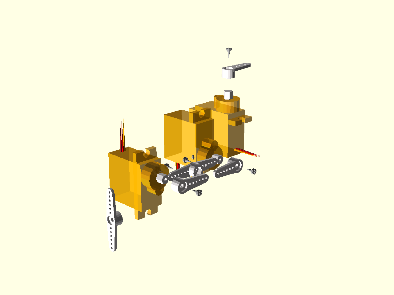
For the tibias, it’s best to use the original, large servo screw. Cut off on side of the “cross” horn, and use the screw to fix it to the servo’s “ear”.
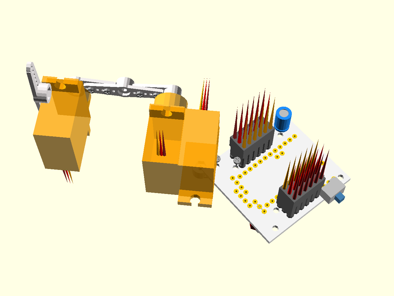
Make sure the servos are all at their center positions, and then assemble the legs by gluing two servos, and putting on the servo horns:
You will need two pairs of legs, one pair normal, and the other the mirror image of the first pair. Attach them to the body at 45° like this:
You will probably need to adjust the horns, so that the robot is in its home position when it starts.