Step-by-step Tutorial
This tutorial should take you through all the steps you need to design a walking robot like the Tote. It’s for people who are not satisfied with just blindly following a ready blueprint, but would rather want to be able to design their own robots. This takes considerably more time, than just assembling a robot, but it can be done one small step at a time.
Soldering the Pin Headers
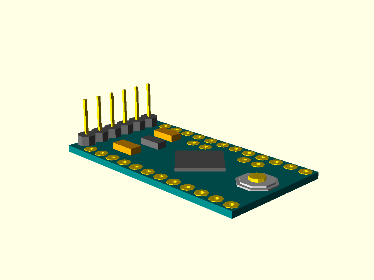
In order to be able to connect your Pro Mini to your computer, you first need to solder the pin header for the serial communication. Your board should have come with with three pin headers: one 6 pins long, and two 12 pins long. You will need the shorter, 6 pin long one. The pins in it may be straight, like in the illustrations, or they may be angled – it doesn’t matter for our purposes.
Insert the pin header into the holes at one of the short ends of the board, as the illustration below shows:
Now flip the board to the other side, place it on a table, and carefully solder each of the pins to their holes. To do that, first touch the hole with the end of your solder wire, and then briefly touch it with a hot soldering iron, as shown below:
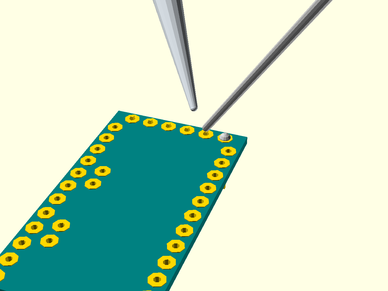
The solder should melt and flow into the hole, filling it and securing the pin in place. Make sure you don’t connect the neighbouring pins with each other while doing this. Each of them should have a separate electric connection only to their own hole.
Connecting the Pro Mini to the Computer
Unlike most other Arduino boards, the Pro Mini cannot be directly connected to your computer’s USB port. Instead, you will need to use a small device called USB2TTL adapter, which basically contains all the electronics required to support a USB connection that the Pro Mini is missing. This makes the Pro Mini much cheaper than the other boards, and you can re-use the adapter for other projects. You will also need a cable to connect the USB2TTL with your board. It’s simply 5 wires, with small sockets on both sides, which slide onto the pins that you just soldered, and onto the pins of the adapter. You have to pay very close attention to which pins you are connecting, though. Look at the symbols on both boards, and connect the pins like this:
- The DTR pin on the Pro Mini connects to the DTR pin on the adapter.
- The TXD (or simply TX) pin connects to the RXD (or RX) pin.
- The RXD (or RX) pin connects to the TXD (or TX) pin.
- The VCC pin connects to the 5V (or VCC) pin.
- The GND pin connects to the GDN pin.
If your adapter lacks the DTR pin, don’t worry, you can skip it, but then you will have to manually restart your board each time you are uploading code into it.
Once you made all the connections, insert the USB2TTL into your computer’s USB port. If everything went right, and your Pro Mini is brand new, you should see one LED on it light up (it’s the power indicator), and another LED blink about once a second. This is the default “demo” program that is uploaded to all new Arduino boards, and it shows that your board is working.
Uploading First Arduino Program
In order to actually write and upload programs onto your board, you will need the Arduino IDE software. You can download it from the Arduino website for your platform of choice. Refer to the information on that website for help with installing and configuring it.
Once you have that working, you can select the “blink” example from the examples menu, select the right board type (Pro Mini 3.3V), connect your board and hit the “upload” button. With a little luck you will have your own “blink” program uploaded. To verify that it works, you can change the delay between blinks, and upload it again.