Inverse Kinematics
Kinematics is the process of determining how a robot will move given certain inputs. Inverse kinematics is for determining what inputs we need to give it to get into a certain position. In particular, leg inverse kinematics for walking robots is the process of calculating the angles for all the joints required to get the tip of the leg in a certain position relative to the body. There is also body inverse kinematics, which tells us in what positions the legs have to be for the body to be in a certain position (tilt, yaw, rotation, shift).
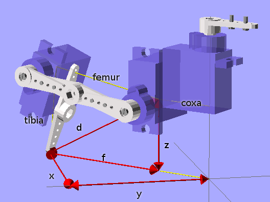
This are notes for determining the inverse kinematics for a four-legged robot with three degrees of freedom per leg. Let’s start with an image of the leg:
Basic Trigonometry
For a start, need to determine the geometry of the leg and describe it using mathematical formulas. For that, we will start with a few tricks from the elementary school.
To calculate the diagonal of a rectangle, we can use the Pitagoras theorem,
 , so
, so 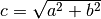 .
.
To calculate one of the angles of a triangle for which we have the lengths of
all sides, we can use the Law of Cosines:  , which gives us
 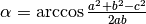 .
.
Finally, to calculate the angle of the diagonal in a rectangle, we have 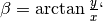 , or better,
 beta = atan2(y, x), as most languages
have a convenience function for this that also handles the sign properly.
Solving a Leg
We are given the coordinates  and we want to calculate the
angles
and we want to calculate the
angles  of the hip, knee and ankle joints. We
also have the lengths of coxa (
of the hip, knee and ankle joints. We
also have the lengths of coxa ( ), femur (
 ) and tibia
(
) and tibia
( ). The hip is easy:
All the rest is happening in one vertical surface along the hip angle, so we
can convert our into  , where
  is the part of the diagonal starting at the knee joint
(see picture).
is the part of the diagonal starting at the knee joint
(see picture).
The knee angle is going to consist of two parts. The first is easy,
 . For the second, we need to know the
lenght of the diagonal
. For the second, we need to know the
lenght of the diagonal  . Once we have
  , we
can solve the triangle formed by tibia and femur, and we get
, we
can solve the triangle formed by tibia and femur, and we get 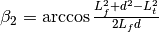 . Finally:

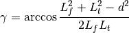
Solving the same triangle, but for a different angle, will give us our ankle angle:
Trim and Reverse
We have the angles, but they are unlikely to have to align with where our physical servomotors have their zero angles, and the direction they turn. So we have to add some offsets to them, and possibly reverse them. The easiest way to go about that is to set all your servos to 0 and check where the end of the leg should be then. Then run those coordinates through our formulas, and you will get the numbers that you have to subtract from our calculated angles (so that at the initial position they are all zero). Then move them a little from the initial position and see if the directions are right.